The Zoom Room Controls page is a quick and easy tool for managing devices. However, sometimes you may prefer more granular control over what happens when a meeting starts or ends. With Parallax Control, you can listen for “Meeting Started” or “Meeting Ended” signals from your Zoom Room Controller. From there, it’s possible to run your own automations using the power of Node-RED or even .NET.
In this example, we’ll demonstrate how to create a Zoom Room Control JSON file that emits “Meeting Started” and “Meeting Ended” events to the control processor. The control processor will then send RS-232 serial commands to the display to turn it on or off, and to the relay to raise or lower the shades. Since everything will be 100% automated, there will be no need for buttons on the Zoom Room Controls page or a control panel. Everything will happen seamlessly behind the scenes.
Required Hardware:
A Zoom Room video conferencing system (compatible with any manufacturer)
Parallax CM4-Pro processor
Other Required Items:
Access to the Zoom Room Admin Web Portal.
Basic knowledge of Node-RED
CM4-Pro should have access to internet to communicate with Zoom.
Required Licenses:
No additional licenses required.
Before you can upload a JSON configuration profile, the setting will need to be enabled for a Zoom Room.
We've created the following JSON configuration which will communicate with our processor and send room call status commands to our processor. Notice this JSON config file for zoom is very basic, we will do all the heavy lifting in Node-RED.
Processor IP: 192.168.1.152
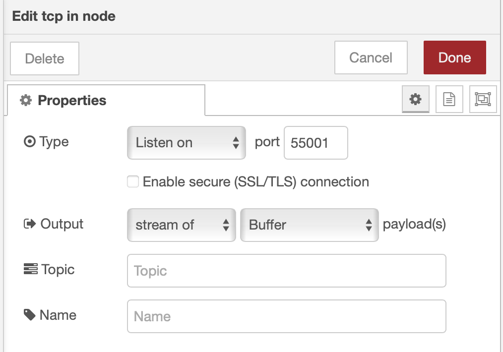
Processor Listening on Port: 55001
{
"adapters": [
{
"model": "GenericNetworkAdapter",
"ip": "tcp://192.168.1.152:55001",
"uuid": "Notifier_1",
"ports": [
{
"id": "meeting_notifier",
"name": "Meeting Notifier",
"methods": [
{
"id": "meeting_started",
"name": "Meeting Started",
"command": "MEETING_STARTED\\r",
"type": "action"
},
{
"id": "meeting_ended",
"name": "Meeting Ended",
"command": "MEETING_ENDED\\r",
"type": "action"
}
]
}
]
}
],
"rules": {
"meeting_started": [
"meeting_notifier.meeting_started"
],
"meeting_ended": [
"meeting_notifier.meeting_ended"
]
}
}
Connect to the controllers IP address and log into the Node-RED dashboard:

Whats happening here:
A TCP server, listening on port 55001, passes incoming messages to the switch statement. If a meeting has started or ended, it will trigger the relay and send a serial command. Notice that the relay is triggered directly by the switch case node, rather than after the serial node. This is because the serial port requires some time to complete its operation. Triggering the relay directly from the switch case reduces delay.

Drop in the TCP In Node.

Add a Switch Node, property is msg.payload. We are checking if the response is "MEETING_STARTED" or "MEETING_ENDED". When a match is found, the corresponding output will go high.

Add a Change Node. We will Set the new output of the change node to msg.payload.Value, and the value to the display power command, in this case "power on\x0D". Do the same for the power off change node, which should be connected to MEETING_ENDED on the switch node.

Add the Parallax Serial Node. Configure the correct settings for the device. The displays command from the previous node will be sent to the RS232 port.

Add another change node (connect to switch statement).
Set msg.payload to the value of type JSON. This will be used to select the input on the relay node, and will be used to drive the relay high or low.
Note that a JSON Object with a boolean Value of true is required to trigger the node. This is to avoid unwanted triggers when automations run as Node-RED nodes will always run on any event.
Turn Relay On: {"Input":1,"Value":true}
Turn Relay Off: {"Input":2,"Value":true}

Add the Relay Node. Note that the relay on the CM4-PRO has 2 channels.
Channel 1 = Port 1 and 2, where Port 1 is ON, port 2 is OFF.
Channel 2 = Port 3 and 4, where Port 1 is ON, port 2 is OFF.

References:
Zoom Room Control page: https://support.zoom.com/hc/en/article?id=zm_kb&sysparm_article=KB0064072